Why does smart pet feeder PCB and IoT design often determine whether a new product becomes a market hit—or a costly headache?
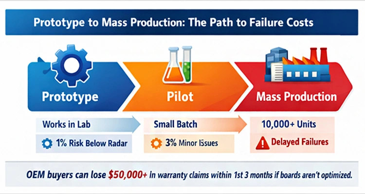
OEM buyers can face losses exceeding $50,000 in warranty claims within the first three months if boards aren’t engineered with long-term reliability in mind. It’s not a matter of “if” a product will fail; it’s a matter of when—usually after the first 3,000–10,000 units reach real homes.
Early-stage failures might show up as missed meals, devices going offline, unstable cameras, or inexplicable resets. These aren’t random glitches—they are the delayed consequences of cutting corners during development.
For brands, the true cost goes beyond a defective circuit board: it manifests as refunds, negative reviews, compliance delays, and a damaged brand reputation painstakingly built over years.
This is precisely why custom PCB and IoT development for smart pet feeders should be treated as both a technical and a business-critical decision. The distinction between a scalable product and a post-launch liability is often set before the first batch leaves the factory.
OEM teams can benefit from insights into how Petrust® designs IoT-ready smart feeders to ensure stable Wi-Fi connections, precise feeding portions, and production that can scale without costly surprises.
Even a well-designed feeder prototype can hide hidden risks. Small design oversights in power management, signal stability, or firmware updates can ripple into large-scale issues once devices are in real homes.
Understanding the interplay of hardware, firmware, and connectivity early on can save brands months of troubleshooting and tens of thousands in lost revenue.
Why Off-the-Shelf Smart Feeder Solutions Often Fail After Mass Production
From Lab Stability to Real-World Challenges
Off-the-shelf reference designs are often built to demonstrate functionality, not to endure the messy realities of daily life: fluctuating power grids, congested Wi-Fi environments, or continuous, non-stop operation.
In the lab, everything works perfectly. In apartments with multiple mesh routers, stray Bluetooth signals, and a mix of smart home devices, issues appear fast and often unexpectedly.
Research on IoT device reliability shows that long-term dependable operation depends on more than passing initial prototype tests. Environmental conditions, electrical noise, and real-world usage patterns all play a role, which is why simple reference designs rarely scale reliably.
These weaknesses only become visible when warranty data starts revealing patterns engineers never anticipated, quietly eating into margins and customer satisfaction.
| Stress Factor | Lab Conditions | Real-World Conditions | Impact on Smart Feeder |
| Power Supply | Stable, clean | Fluctuating, noisy | Micro-resets, skipped feed |
| Wi-Fi | Low interference | Mesh routers, multiple devices | Dropped connections, video lag |
| Temperature | Controlled | Ambient variations, heat accumulation | Thermal throttling, component aging |
| Mechanical Wear | Minimal | Continuous daily operation | Portion inconsistency, motor backlash |
| Environmental Noise | Low | RF interference, electronics nearby | Wi-Fi instability, sensor errors |
How Early Hardware Decisions Turn Into Post-Launch Problems
Generic boards often ignore regional power standards, enclosure constraints, and antenna placement realities.
Once tooling and production setups are locked, these early compromises are expensive—or impossible—to correct, creating ongoing post-launch failure risks in smart pet feeders.
A real-world example: one OEM client experienced a 7% failure rate caused by inadequate Wi-Fi PCB design before switching to a custom approach. This highlights how early design choices ripple across thousands of units, turning small engineering shortcuts into major business headaches.
How Smart Pet Feeder PCB and IoT Design Reduces Post-Launch Failures
Hardware-Level Decisions That Drive Long-Term Reliability
Reliable products start at the board level. Purpose-built PCBs consider component derating, signal isolation, and thermal margins—essential pillars of long-term reliability in smart feeder manufacturing.
This is why custom hardware development for smart pet feeders is so critical: it allows boards to be tailored to the product’s actual operating environment rather than theoretical conditions.
Translating Engineering Risks Into Business Outcomes
Every unstable feeder generates support tickets. Every support ticket costs money—not just in refunds, but in brand reputation and lost customer trust.
When multiplied across thousands of units, poor hardware decisions quietly erode profitability, even when the app experience looks polished.
Smart Pet Feeder PCB Design: Where Feeding Accuracy Truly Happens
Feeding Accuracy Controlled at the Hardware Level
Precision feeding is less about software logic and more about robust control system design. Motor drivers, load sensors, and timing circuits live on the board. Weak designs drift over time, producing portion inconsistency that customers notice immediately.
This is why firmware and hardware co-design is essential: software must complement electrical behavior, not fight it. You might find smart feeder co-design frameworks helpful when aligning engineering decisions with real-world outcomes.
Power Stability, Motor Control, and Portion Consistency
Voltage dips during motor startup can trigger micro-resets or skipped steps, silently degrading feeding accuracy. Without strong regulation and isolation, each batch risks incremental failure.
At this point, PCB design alone is not enough—mechanical execution matters. Motor backlash, auger tolerance, and torque consistency all directly influence portion control.
Integrating motor & auger control engineering for consistent feeding becomes the next critical layer for OEM buyers seeking scalable, reliable products.
IoT Architecture for Smart Pet Feeders: Why Connectivity Issues Keep Happening
Connectivity problems in smart pet feeders often frustrate brands more than end-users realize. The root cause rarely lies in the cloud or app; it usually starts at the hardware level.
Even the most sophisticated software can’t compensate for boards that weren’t built to handle real-world wireless challenges.
Wi-Fi Connectivity Stability in Smart Feeders
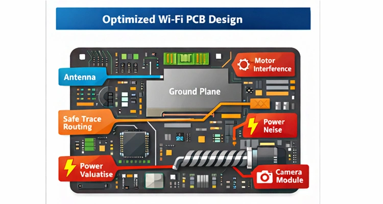
Many complaints about disconnections trace back to antennas, trace routing, and ground planes rather than network issues. Boards with overlooked design details often carry board-level issues that manifest as constant offline reports or unreliable device behavior.
Industry research and professional antenna design resources emphasize that performance, efficiency, and environmental integration must all be balanced to maintain stable wireless communication.
A thoughtfully optimized PCB layout for Wi-Fi performance ensures signals remain robust, even when multiple devices compete for bandwidth or environmental interference is high.
For feeders that include video features, connectivity becomes even more delicate. Factors such as camera bandwidth, shielding, and heat dissipation all interact with RF performance.
Many OEM teams find it helpful to consider smart feeder camera module selection early in the design phase when planning Wi-Fi camera smart feeder development, preventing surprises after mass production.
PCB Design for Wi-Fi Enabled Pet Devices
Adding cameras or other IoT modules multiplies the complexity. Wi-Fi camera smart feeder development requires meticulous bandwidth planning and shielding to prevent dropped streams, overheating, or inconsistent operation during continuous use.
Neglecting these details often turns into costly support calls and returns once devices reach real homes.
Why Custom PCB and IoT Development for Smart Pet Feeders Matters More Than App Optimization
Hardware vs Software Responsibility in Connectivity Failures
Hardware decisions define the ceiling of reliability, while software can only polish the experience. Apps cannot compensate for weak power rails, poor RF isolation, or under-engineered boards.
Cost-driven shortcuts often force engineers to mask problems in software—often unsuccessfully, creating hidden risks that surface in large-scale deployments.
Strong RF interference mitigation in smart feeders must be engineered into the PCB from day one. Relying solely on firmware improvements or cloud integration cannot resolve fundamental reliability issues.
You might find firmware & cloud app strategy for smart feeders helpful for understanding where software can complement, rather than replace, robust hardware design.
When Cost-Driven PCB Compromises Break User Experience
Cutting corners on components to save pennies can easily cost dollars in returns. Once negative reviews mention “offline feeder” or “missed feeding,” brand trust suffers—regardless of a polished user interface or app experience.
Investing in well-engineered boards prevents small cost savings from turning into large reputational losses.
Low Power PCB Design for Pet Feeders and Long-Term Product Reliability
Power Management Challenges in Always-On Smart Feeders
Smart feeders operate continuously. Cameras, sensors, and Wi-Fi modules draw constant current, making inefficient power design highly visible.
According to a 2025 study on the energy footprint and reliability of IoT communication protocols, minimizing energy consumption in wireless transmitters significantly improves operational longevity for devices that must remain continuously connected—even under heavy use.
A solid power management design for IoT pet devices helps prevent thermal stress, battery drain (in backup modes), and premature component aging, protecting both reliability and brand reputation over time.
How Energy Inefficiency Increases After-Sales Costs
Excess heat accelerates component failure. Failure leads to returns. Returns erode profit. Effective low-power PCB design isn’t just a technical feature—it acts as a financial safeguard, ensuring your product maintains performance, customer satisfaction, and profitability throughout its lifecycle.
Custom PCB and IoT Development for Smart Pet Feeders in Mass Production Environments
Scaling a smart pet feeder from a few prototypes to thousands of units in homes worldwide is where engineering choices reveal their true impact.
Custom PCB and IoT development for smart pet feeders isn’t just about getting the lights to blink or Wi-Fi to connect—it’s about creating hardware that survives daily use, firmware updates, and real-world environments without turning into a liability.
Mass Production Ready PCB Design vs Prototype Engineering
Prototypes are exciting—they prove concepts. Production-ready boards protect businesses. Designs intended for mass production must account for tolerance stacking, supplier variation, and testability, all of which are core requirements for OEM-ready smart feeder hardware.
Recognizing how early PCB decisions influence cost, yield, and scalability is a critical part of OEM smart feeder production insights. Experienced partners like Petrust® embed manufacturability, reliability, and compliance into every design, allowing brands to scale predictably rather than reacting to surprises after launch.
Hardware-Software Integration for OEM Feeders at Scale
Once volumes grow, firmware updates, calibration consistency, and QA workflows must align tightly with hardware realities. A mature smart pet feeder product development process ensures that engineering choices remain consistent from pilot runs through container shipments.
This alignment minimizes costly post-production fixes, maintains customer satisfaction, and protects your brand’s reputation.
Certification-Ready Hardware Design: CE, FCC, and Global Compliance
RF, EMI, and Power Design Considerations for FCC Approval
Certification challenges rarely arise from missing paperwork—they usually originate in hardware design. Emissions, grounding, and clock noise can all cause failures.
Designing with hardware design for global certification (CE, FCC) in mind from day one prevents expensive redesigns and avoids missing critical selling windows.
Why Certification Issues Often Start at the PCB Level
Waiting until late-stage testing to address EMI or RF issues often means costly re-spins. Early foresight avoids delays and keeps your launch schedule intact.
OEM buyers might find certified cat feeder compliance checklist helpful to guide procurement and ensure hardware aligns with certification expectations.
Evaluating Smart Pet Feeder PCB and IoT Design Before Choosing an OEM Partner
Questions OEM Buyers Should Ask About Smart Pet Feeder PCB and IoT Design
Critical questions include: who owns schematics, how RF testing is handled, and whether designs are flexible enough for smart cat feeder OEM customization.
Real OEM smart feeder manufacturers in China answer these confidently and can demonstrate how thoughtful engineering decisions protect your brand after launch.
Red Flags That Signal Assembly-Only Manufacturers
Suppliers who cannot clearly explain power architecture, antenna tuning, or compliance strategy are assembling—not engineering. This distinction is crucial: it determines whether your product scales or struggles.
Investing in partners who understand the full picture keeps your launch smooth and supports long-term growth.
FAQ / Buyer Tips
What are the most important questions to ask about PCB customization?
Understanding schematics ownership, RF testing procedures, component sourcing, and how firmware aligns with hardware is critical.
These details often reveal whether a supplier treats custom PCB and IoT development for smart pet feeders as a strategic advantage or just an assembly task.
How can Wi-Fi stability be assured before mass production?
You can request antenna placement diagrams, board-level Wi-Fi testing results, and real-world load testing reports. These insights give a clearer picture of whether the feeder will remain reliable in homes with multiple devices or challenging network conditions.
How do you identify an OEM that truly prioritizes engineering quality over simple assembly?
Pay attention to suppliers who provide thoughtful explanations of tolerance stacking, signal isolation, and regulatory compliance planning. These are often the subtle signals that show how seriously they treat long-term reliability.
Conclusion
In smart pet feeders, hardware isn’t just a line item—it’s a moat that protects your brand and customer experience. Investing in custom PCB and IoT development for smart pet feeders reduces risk, controls quality, and builds products that survive real-world use at scale.
For buyers comparing potential partners, the focus should shift beyond pricing. Benchmark engineering depth, not just unit price, and you might find top OEM smart feeder partners in China helpful as a reference point when assessing capability and reliability.
To take your evaluation one step further, download our OEM Smart Feeder PCB Checklist. This tool helps you systematically assess suppliers, ensuring that your next smart feeder launch avoids the costly and stressful failures that often emerge after production.